
Monday, December 10, 2018
Creating Geometry Pattern in Autodesk FORGE Viewer
By
Sadashiv Khadilkar
Patterns
Patterning is very useful and necessary tool/feature while CAD modelling. It has made life easy for designers. Most CAD software includes this functionality. By combining multiple pattern operations, you can achieve very complex results easily.
Why we needed patterns?
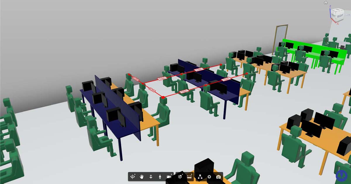
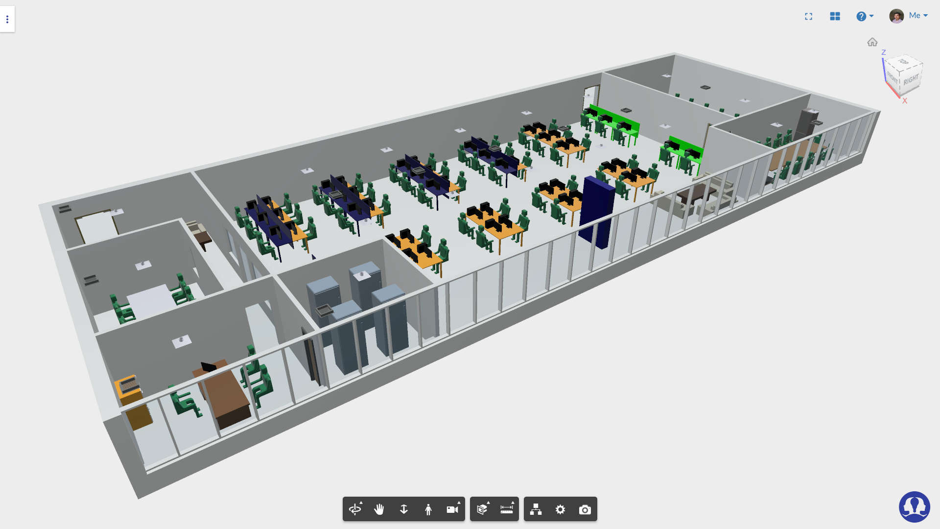
Our product simulationHub, uses Autodesk FORGE viewer for visualization of CFD simulation. In our upcoming thermal comfort analysis app, we needed human heat load manipulation option. For this we implemented rectangular grid and circular grid patterns.
How we implemented pattern feature in Autodesk FORGE viewer?
TFor creating grid pattern, following inputs were used.
1Selective area on which to create pattern
2Number of objects row and column wise
Rectangular region can be specified by selecting two points which are diagonally opposite corners of rectangle. After selection we divided the rectangle based on number of objects into grid. These grid point locations will be used for pattern.
function rectangularDistribution(cornerPointArray, numDivisionArray) {
    distributionPointArray = [];
    for (var i = 0; i < numDivisionArray[0]; i++) {
        for (var j = 0; j < numDivisionArray[1]; j++) {
            var point = cornerPointArray[0].clone();
            var param1 = i / numDivisionArray[0];
            var param2 = j / numDivisionArray[1];
            point.x = cornerPointArray[0].x * (1 - param1) + cornerPointArray[1].x * param1;
            point.z = cornerPointArray[0].z * (1 - param2) + cornerPointArray[1].z * param2;

            distributionPointArray.push(point);
        }
    }
    return distributionPointArray;
}
Similarly, for circular pattern, area can be selected by supplying circle center and point on circumference. Here the divisions will be angular and radial. We generate grid point locations by dividing the circular region selected.
function radialDistribution(circlePoints, angularDivisions, radialDivisions) {
    distributionPointArray = [circlePoints[0]];
    var deltaTheta = 2 * Math.PI / angularDivisions;

    for (var i = 0; i < angularDivisions; i++) {
        var rotMatrix = new THREE.Matrix4().makeRotationY(i * deltaTheta);
        for (var j = 1; j < radialDivisions; j++) {
            var param = j / radialDivisions;
            var startPt = circlePoints[0].clone();
            var point = startPt.lerp(circlePoints[1], param).sub(circlePoints[0]);
            point.applyMatrix4(rotMatrix);
            point.add(circlePoints[0]);
            distributionPointArray.push(point);
        }
    }
    return distributionPointArray;
}
Once we get the array of locations where we want to repeat the object, the next step is very easy one. We load the object repetitively and translate to every grid point location. From normal of selected region, we can get the direction to orient the object correctly on selected surface. And we are done!!
function createPattern(viewer, model, patternType, direction, numObjects, distBetweenObjects) {
    var transMat = viewer.impl.getRenderProxy(model, 0).matrixWorld;
    var newTransMat = transMat.clone();
    var modelURN = model.getData().urn;

    viewer2.LoadModel(modelURN).then(function (modelCopy) {
        customGeometries.push(modelCopy);
        const fragCount = model.getFragmentList().fragments.fragId2dbId.length;

        //fragIds range from 0 to fragCount-1
        for (var fragId = 0; fragId < fragCount; ++fragId) {

            var fragProxy = SHub.Globals.viewer.impl.getFragmentProxy(modelCopy, fragId);
            var transformMat = viewer.impl.getRenderProxy(model, fragId).matrixWorld;

            fragProxy.getAnimTransform();
            var position = new THREE.Vector3();
            var quaternion = new THREE.Quaternion();
            var scale = new THREE.Vector3();

            transformMat.decompose(position, quaternion, scale);

            fragProxy.position = position;
            fragProxy.scale = scale;
            fragProxy.quaternion = quaternion;

            fragProxy.updateAnimTransform();
        }

        SHub.Globals.viewer.impl.sceneUpdated(true);

        var bbox = modelCopy.getBoundingBox();
        var translatePt = new THREE.Vector3(bbox.size().x, 0, 0);

        var transformManager = new SHub.Core.TransformManager();
        transformManager.TranslateModel(modelCopy, translatePt);
        viewer.impl.sceneUpdated(true);

    }).catch(function (err) {
        console.log(err);
    });
}
This example illustrates the pattern generation for specific use case, but same patterning logic can be used anywhere with minor modifications. You can implement other patterns like linear, arc etc. using similar logic.
About author
Sadashiv Khadilkar
Sadashiv is a Senior Member of Technical Staff at Centre for Computational Technologies Private Limited (CCTech), Pune. He loves problem solving, optimization and is interested in artificial intelligence, high performance computing, web technologies. He has experience in C++, Javascript, Python, C#. He holds a Bachelor's degree in Computer Science and Technology from Shivaji University, Kolhapur.
Comments
Recent posts