





Tuesday, November 03, 2026
How Agentic AI and MCP Servers Close the CAD Design-to-Manufacturing Loop
By
Aditi Mane
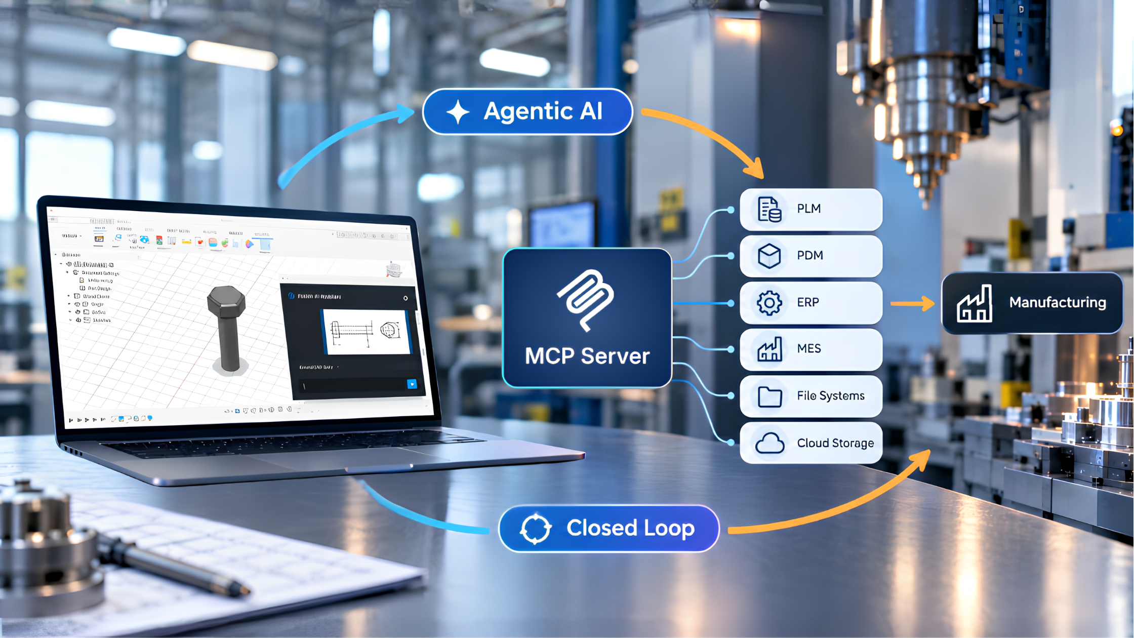
Close the Gap Between CAD Design and Manufacturing Decisions
Every product design process travels the same road in the manufacturing industry. Initially, the design intent becomes geometry, and geometry must be judged against what the factory can build. However, both conversions are slow, expensive if rework is required, and require an experienced specialist with undivided attention.
Let's consider a scenario, what if an engineer initiates a conversational workflow and could describe a part in natural language, generate an editable CAD model, ask whether it can actually be manufactured, receive recommendations grounded in factory data, and apply those recommendations?
CCTech's Emerging Tech team has explored this engineering challenge through two Proofs of Concept (POCs). We explored how AI participates in the design-to-manufacturing workflow rather than simply assist with one step of it:
- An agentic AI pipeline that turns a drawing or a sentence into a parametric solid body inside a live Fusion 360 session.
- A set of Model Context Protocol (MCP) tools that turn a CAD model into a scored, sourced, factory-aware judgement.
The two POCs, developed independently, address complementary gaps in the DFMA (Design for Manufacturing and Assembly) workflow: the first turns design intent into geometry, and the second evaluates that geometry for manufacturability and assembly. Connected, they would deliver DFMA feedback at the point of design rather than late in review.
Let us understand the need for this connection in the first place using a use case.
The Gap Between Design Generation and Manufacturing Validation
Consider an engineer designing a mounting bracket for a production volume of 2,000 units per year.
The engineer begins with a scanned 2D drawing and interprets dimensions from the front, top, and side views. After creating the CAD model, the design is evaluated for wall thickness, draft, features, tolerances, material suitability, assembly efficiency, manufacturing process, cost, and factory availability.
Today, these decisions often span multiple systems and require expertise across various areas. CAD data, manufacturing rules, material properties, and ERP records are frequently disconnected. Manufacturing review may also depend on a specialist being available precisely when a design decision is made.
This creates two fundamental problems.
- The cost of generating and modifying CAD models often discourages engineers from exploring alternative designs.
- Design evaluations often yield manufacturing recommendations that still require specialist input for implementation.
The two POCs attack these problems from opposite directions. This is where Agentic AI comes into action. Rather than treating AI as a one-shot design generator, an agent can maintain workflow context, decide what action is required next, use specialized tools, verify the result, and recover when an operation fails.
An Agentic CAD Generation Pipeline
The first POC explores Fusion AI Assistant. It is designed to convert a natural-language description or 2D engineering drawing into an editable parametric solid within a live Fusion 360 session.
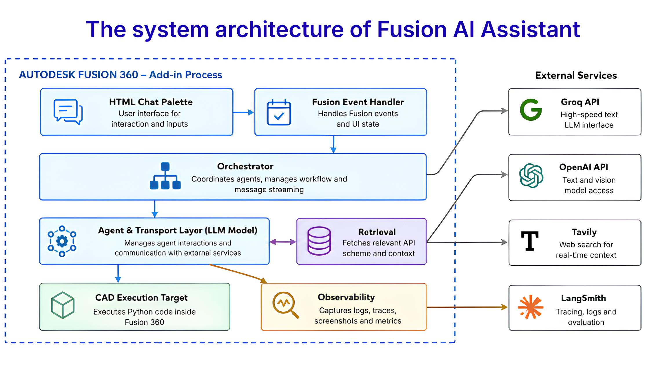
Fig.1 The system architecture of Fusion AI Assistant
Initially, the user enters the request through the HTML chat palette, which is routed to the orchestrator via the Fusion event handler. Orchestrator manages agent execution, workflow state, and message streaming. For reasoning and code generation, the LLM model including agent and transport layer manages interaction with external services. The retrieval component fetches relevant Fusion API context and schema for each modeling step. The LLM model sends the code to the execution target within Fusion 360 to create or modify CAD geometry. During execution, observability captures logs, traces, screenshots, and performance data to support debugging and visual QA. External services utilized between each phase of the workflow generate text and vision inference, web-based modeling context, and system tracing.
These components enable a controlled, iterative agentic pipeline moving from user intent to planning, code generation, CAD execution, and verification.
What makes the agentic workflow useful for engineering?
Multi-agent workflow- The system runs ten specialized agents to produce the final outcome in one shot.
Controlled API Access — Failure-prone patterns are blocked with controlled Fusion API access and curated CAD operations.
Step-Level Retrieval — Only the most relevant API context is retrieved for each modelling step.
Parametric Output — Generated designs are kept editable and physical dimensions become named Fusion parameters.
The result is a dependable agentic CAD workflow capable of generating, verifying, and altering designs. In POC 01, genuine, editable bodies were successfully created from both text and drawing inputs. Prismatic geometry, such as plates, blocks, bosses, holes, cuts, and simple stepped or slanted profiles proved to be the most reliable approach, while restricting the API surface was found to be more useful than constantly improving the prompts
Generating geometry solves the problem of engineering design. It becomes useful only when it can be evaluated against the constraints of manufacturing, assembly, materials, cost, and the factory that will produce it.
This is where the second POC enters.
MCP Servers for CAD Intelligence in Manufacturing
Once the design is generated using the Fusion AI assistant, another question that arises is -
Can the design actually be manufactured at the required volume, using available materials and equipment?
Yes, two servers built on the MCP have demonstrated that the design can be manufactured as required. The Design for Manufacturing and Assembly (DFMA) and Ashby MCP servers provide expert-level manufacturability, material, and cost guidance in plain conversation. The core purpose to choose MCP lies behind the idea of allowing AI to select the optimal parameters and provide respective explanation in plain English. Standard plumbing lets a chat assistant discover and call external tools with typed inputs and in return, Claude Desktop supplied the client, transport, and retry logic that POC 01 had to hand-build itself.
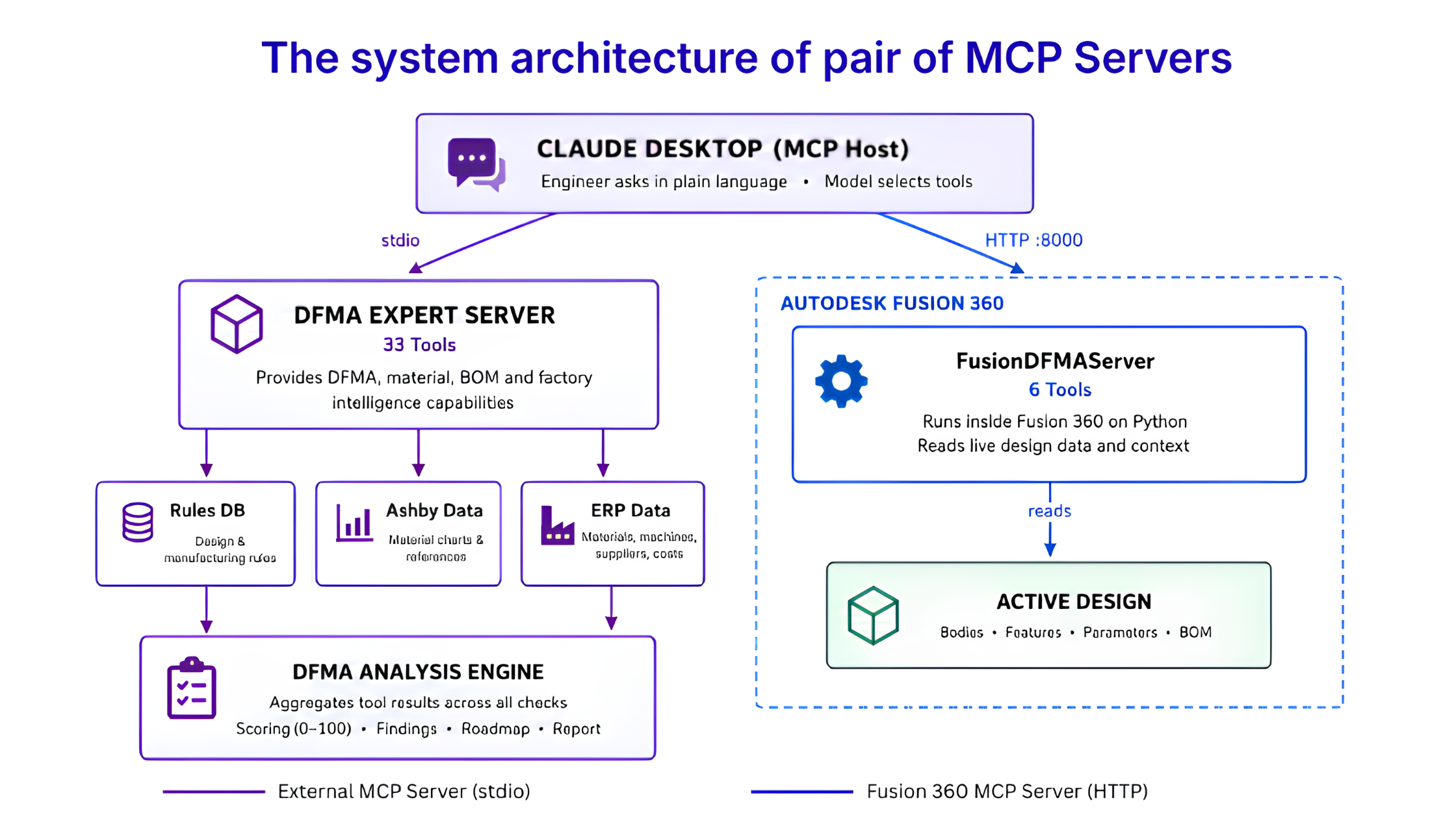
Fig.2 The system architecture of pair of MCP Servers
We built 33 deterministic tools of MCP, which spans across manufacturing, assembly, BOM, materials, and enterprise data. They enable analysis of wall thickness, draft, tolerances, process selection, part necessity, fasteners, cost, supply risk, material properties, machine availability, inventory, supplier lead times, and job costs.
The workflow uses Ashby-based material analysis along with enterprise data, such as material stock and price, supplier lead times, machine availability, hourly rates, and backlog. Instead of relying on the LLM for engineering calculations, MCP tools apply set rules and calculations to produce structured results. These results are combined into a DFMA score from 0 to 100, prioritized recommendations, and a traceable report. This process turns a CAD model into useful engineering insights.
MCP acts as a bridge between the two systems. The AI host manages the workflows and communicates with the MCP servers through predefined input formats. While the MCP servers return engineering findings in a structured JSON format. This allows the AI to interpret the results, explain recommendations, and use them in subsequent design modifications.
Integrating Agentic AI and MCP-Based Intelligence in Closed Loop
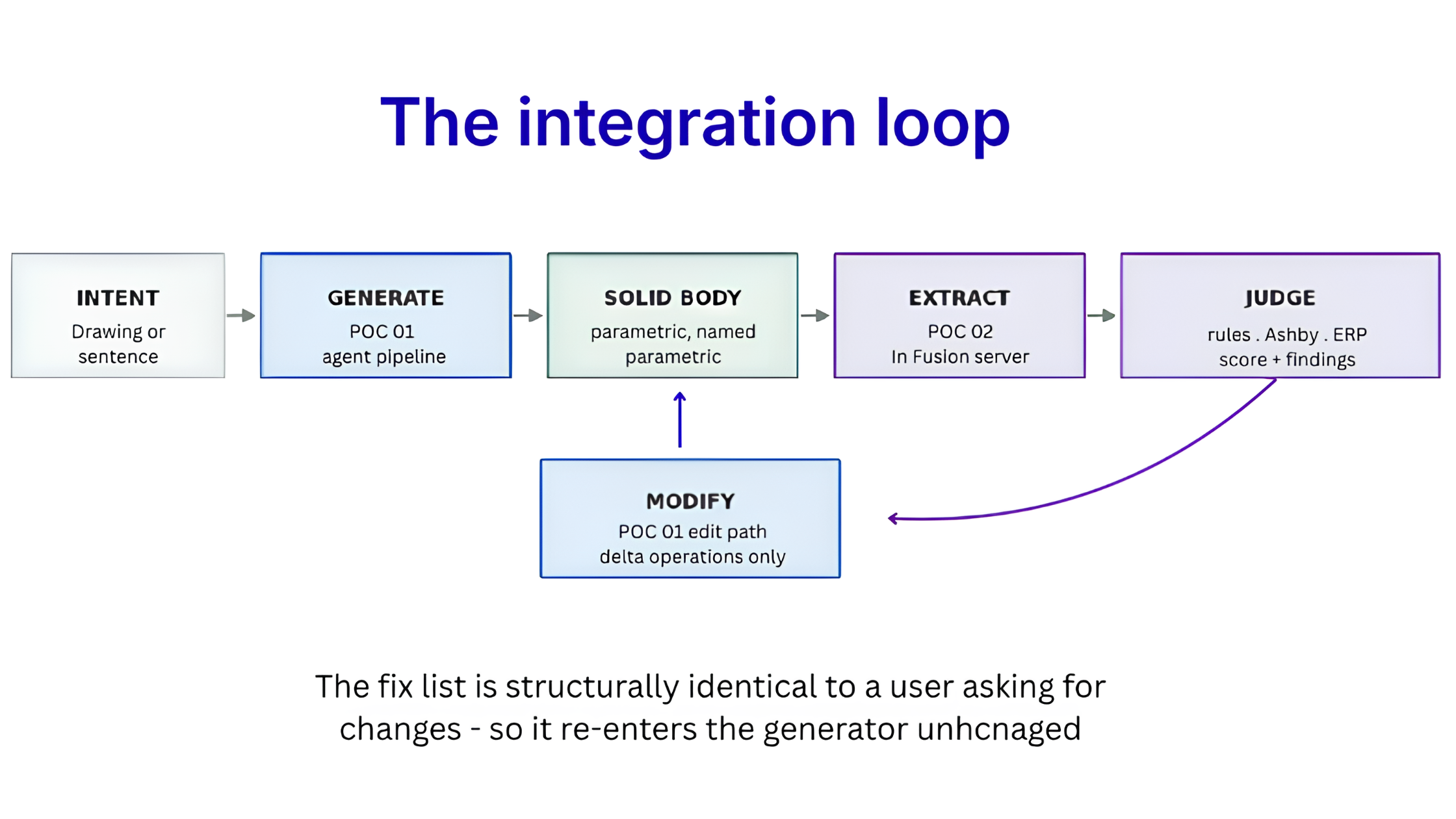
Fig.3 The integration loop
Suppose a recommendation is received from the DFMA analysis. It identifies a rib that is too thin or a vertical wall that needs a draft angle for easier manufacturing. It recommends increasing the rib thickness or adding a slight taper to the wall to make the design more suitable for manufacturing.
| Without the AI-driven loop (Conventional Workflow) | With the integrated workflow |
|---|---|
| The analysis identifies the problem and stops the process. An engineer reopens the CAD file, finds the right face, and remodels it manually before the design can be checked again. | The same finding becomes an instruction to the agent. It changes a named parameter and adds a draft to a named wall. The design is updated. The MCP servers re-read and re-score it immediately. |
Results and Engineering Learnings
The two POCs produced complementary results and, more importantly, exposed the engineering considerations required to make an agentic CAD workflow reliable and useful in practice.
| What the POCs showed | Engineering takeaway |
|---|---|
| Agentic CAD generation works with text/drawing inputs, parametric output, iteration, recovery, and visual verification. | Constrain the agent with curated tools and API boundaries. |
| Deterministic analysis is repeatable: POC 02 achieved 35/37 tests, while four manufacturing checks and process ranking ran in <1 ms. | Keep engineering logic outside the LLM for repeatability and auditability. |
| Verification has limits: visual checks can miss small errors, and some POC 02 inputs are not yet extracted automatically from geometry. | Verify early and locally to isolate and repair failures. |
| ERP data adds factory context through stock, price, suppliers, lead times, and machine availability. | Ground recommendations in enterprise data. |
| Agentic workflows can involve several dozen model calls for a single part. | Instrument from the start to track latency, retries, failures, and token usage. |
Conclusion
These two proof-of-concept systems illustrate complementary roles for AI in engineering.
Agentic AI interprets user intent, plans, and executes CAD workflows. In contrast, the MCP integrates these workflows with deterministic engineering tools, enterprise data, and real-time application states.
Together, these systems reduce the gap between design generation and engineering feedback, transforming a traditionally fragmented workflow into a conversational and iterative process. That is the shift from AI that assists with engineering tasks to AI that participates in the engineering loop.
About author
Aditi Mane
Aditi Mane is a Software Development Engineer at CCTech’s Emerging Technologies team, focusing on developing AI-driven engineering solutions. She identifies complex, repetitive workflows and uses artificial intelligence and machine learning to simplify, automate, and optimize them. With a keen interest in AI/ML applications in CAD/CAM, she bridges traditional engineering practices with emerging technologies to enhance efficiency, productivity, and innovation.
Comments
Recent posts