
Friday, September 27, 2013
Shading Normals using OpenGL - Graphics Programming
By
Sandip Jadhav
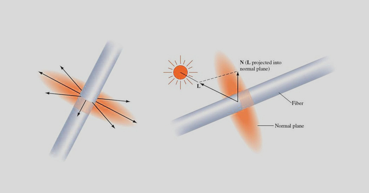
OpenGL computes surface shading by evaluating lighting equations at polygon vertices.
The most general form of the lighting equation uses both the vertex position and a vector that is normal to the object's surface at that position; this is called the normal vector. Ideally, these normal vectors are captured or computed with the original model data, but in practice there are many models that do not include normal vectors.
Given an arbitrary polygonal model without precomputed normals, it is easy to generate polygon normals for faceted shading, but a bit more difficult to create correct vertex normals when smooth shading is desired. Computing the cross-product of two edges, then normalizing the result, yields a unit-length vector, N called a facet normal.
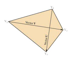
Computing the facet normal of a polygon with more than three vertices is more difficult. Often such polygons are not perfectly planar, so the result may vary depending on which three vertices are used. If the polygon is a quadrilateral, one good method is to take the cross product of the vectors between opposing vertices.
For polygons with more than four vertices it can be difficult to choose the best vertices to use for the cross product. One method is to to choose vertices that are the furthest apart from each other, or to average the result of several vertex cross products.
Smooth Shading
To smoothly shade an object, a given vertex normal should be used by all polygons that share that vertex. Ideally, this vertex normal is the same as the surface normal at the corresponding point on the original surface. However, if the true surface normal isn't available, the simplest way to approximate one is to add all (normalized) normals from the common facets then renormalize the result. This technique was developed by Gouraud in 1971 and therefore also know as Gouraud Shading. This provides reasonable results for surfaces that are fairly smooth, but does not look good for surfaces with sharp edges.
In general, the polygonal nature of models can be hidden by smoothing the transition between adjacent polygons. However, an object that should have hard edges, such as a cube, should not have its edges smoothed. If the model doesn't specify which edges are hard, the angle between polygons defining an edge, called the crease angle, may be used to distinguish hard edges from soft ones.
The value of the angle that distinguishes hard edges from soft can vary from model to model. It is fairly clear that a 90-degree angle nearly always defines a hard edge, but the best edge type for a 45-degree crease angle is less clear. The transition angle can be defined by the application for tuning to a particular model; using 45 degrees as a default value usually produces good results.
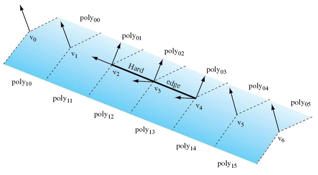
The angle between polygons is determined using the dot product of the unit-length facet normals. The value of the dot product is equal to the cosine of the angle between the vectors. If the dot product of the two normals is greater than the cosine of the desired crease angle, the edge is considered soft, otherwise it is considered hard. A hard edge is created by generating separate normals for each side of the edge. Models commonly have a mixture of both hard and soft edges, and a single edge may transition from hard to soft. The remaining normals common to soft edges should not be split to ensure that those soft edges retain their smoothness.
Above figure shows an example of a mesh with two hard edges in it. The three vertices making up these hard edges, v2, v3, and v4, need to be split using two separate normals. In the case of vertex v4, one normal would be applied to poly02 and poly03 while a different normal would apply to poly12 and poly13. This ensures that the edge between poly02 and poly03 looks smooth while the edge between poly03 and poly13 has a distinct crease. Since v5 is not split, the edge between poly04 and poly14 will look sharper near v4 and will become smoother as it gets closer to v5. The edge between v5 and v6 would then be completely smooth. This is the desired effect.
For an object such as a cube, three hard edges will share one common vertex. In this case the edge-splitting algorithm needs to be repeated for the third edge to achieve the correct results.
Vertex Ordering
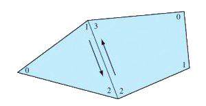
Some 3D models come with polygons that are not all vertex order in a clockwise or counterclockwise direction, but are a mixture of both. Since the polygon winding may be used to cull back or front-facing triangles, for performance reasons it is important that models are made consistent; a polygon vertex order inconsistently with its neighbors should have its vertex order reversed. A good way to accomplish this is to find all common edges and verify that neighboring polygon edges are drawn in the opposite order.
To rewind an entire model, one polygon is chosen as the seed. All neighboring polygons are then found and made consistent with it. This process is repeated recursively for each reoriented polygon until no more neighboring polygons are found. If the model is a single closed object, all polygons will now be consistent. However, if the model has multiple unconnected pieces, another polygon that has not yet been tested is chosen and the process repeats until all polygons are tested and made consistent.
To ensure that the rewound model is oriented properly (i.e., all polygons are wound so that their front faces are on the outside surface of the object), the algorithm begins by choosing and properly orienting the seed polygon. One way to do this is to find the geometric center of the object: compute the object’s bounding box, then compute its mid-point. Next, select a vertex that is the maximum distance from the center point and compute a (normalized) out vector from the center point to this vertex. One of the polygons using that vertex is chosen as the seed. Compute the normal of the seed polygon, then compute the dot product of the normal with the out vector. A positive result indicates that seed is oriented correctly. A negative result indicates the polygon’s normal is facing inward. If the seed polygon is backward, reverse its winding before using it to rewind the rest of the model.
[Adapted from Advanced Graphics Programming Using OpenGL by TOM McREYNOLDS, DAVID BLYTHE. Original book is copyright holder of the images and content. Article partially reproduces content for education purpose only]
About author
Sandip Jadhav
Sandip is a successful serial entrepreneur in CAx space. He co-founded CCTech, LearnCAx, Zeus Numerix, and Adaptive 3D Technologies in the span of last twelve years. Sandip has more than 15 years of product development experience, in the field of CAD, CAM and CFD. He has done major contribution in conceptualizing, designing, and developing 3D CAD application, faceted geometry kernel, faceted Boolean, mesh generation software with automatic fluid volume extraction for dirty CAD assemblies.
Comments
Recent posts