
Sunday, April 13, 2014
Selection in CAD Using OpenGL Graphics Programming
By
Sandip Jadhav
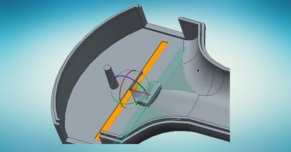
For any CAD developer who is developing interactive CAD application one of the important topic of interest is Selection or Picking. However this topic is not discussed in detailed in most of the OpenGL resources. I hope this article helps you understand basic techniques available for selection. The geometric models use complex representations such as NURBS surfaces and geometric solids that are typically converted to simpler representations for display.
Representations for even relatively simple real-world objects can involve millions of primitives. Displaying and manipulating large models both efficiently and effectively is a considerable challenge. Besides the display of the model, CAD applications must also supply other information such as labels and annotations that can also challenge efficient display. Primarily concerned here is with the display and interactive manipulation parts of the application.
Picking
Interactive selection of objects, including feedback, is an important part of modeling applications. OpenGL provides several mechanisms that can be used to perform object selection and highlighting tasks.
OpenGL Selection
OpenGL supports an object selection mechanism in which the object geometry is transformed and compared against a selection subregion (pick region) of the viewport.The mechanism uses the transformation pipeline to compare object vertices against the view volume.
Objects are identified by assigning them integer names using glLoadName. Each object is sent to the OpenGL pipeline and tested against the pick region. If the test succeeds, a hit record is created to identify the object. The hit record is written to the selection buffer whenever a change is made to the current object name. An application can determine which objects intersected the pick region by scanning the selection buffer and examining the names present in the buffer.
Following simple code demonstrate use of glLoadName :
glInitNames();
glPushName(0);
glPushMatrix(); /* save the current transformation state */
for(int i=0;i<n;i++) {
     glLoadName(1+i);
     drawEntity(i);
}
glPopMatrix (); /* restore the previous transformation state*/
Following are the important OpenGL name manipulation API used selection mode:
void glInitNames(void);
//Clears the name stack so that it's empty.
void glPushName(GLuint name);
//Pushes name onto the name stack.
void glPopName(void);
//Pops one name off the top of the name stack.
void glLoadName(GLuint name);
/*Replaces the value on the top of the name stack with name. If the stack is empty, which it is right after glInitNames() is called, glLoadName() generates the error GL_INVALID_OPERATION. To avoid this, if the stack is initially empty, call glPushName() at least once to put something on the name stack before calling glLoadName().*/
The OpenGL selection method determines that an object has been hit if it intersects the view volume. Bitmap and pixel image primitives generate a hit record only if a raster positioning command is sent to the pipeline and the transformed position lies within the viewing volume. To generate hit records for an arbitrary point within a pixel image or bitmap, a bounding rectangle should be sent rather than the image. This causes the selection test to use the interior of the rectangle. Similarly, wide lines and points are selected only if the equivalent infinitely thin line or infinitely small point is selected. To facilitate selection testing of wide lines and points, proxy geometry representing the true footprint of the primitive is used instead.
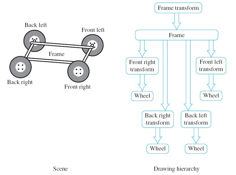
Many applications use instancing of geometric data to reduce their memory footprint. Instancing allows an application to create a single representation of the geometric data for each type of object used in the scene. If the application is modeling a car for example, the four wheels of the car may be represented as instances of a single geometric description of a wheel, combined with a modeling transformation to place each wheel in the correct location in the scene. Instancing introduces extra complexity into the picking operation. If a single name is associated with the wheel geometry, the application cannot determine which of the four instances of the wheel has been picked. OpenGL solves this problem by maintaining a stack of object names. This allows an application, which represents models hierarchically, to associate a name at each stage of its hierarchy. As the car is being drawn, new names are pushed onto the stack as the hierarchy is descended and old names are popped as the hierarchy is ascended. When a hit record is created, it contains all names currently in the name stack. The application determines which instance of an object is selected by looking at the content of the name stack and comparing it to the names stored in the hierarchical representation of the model.
Using the car model example, the application associates an object name with the wheel representation and another object name with each of the transformations used to position the wheel in the car model. The application determines that a wheel is selected if the selection buffer contains the object name for the wheel, and it determines which instance of the wheel by examining the object name of the transformation.
Object Instancing and selection
Figure shows an illustration of a car frame with four wheels drawn as instances of the same wheel model. The figure shows a partial graph of the model hierarchy, with the car frame positioned in the scene and the four wheel instances positioned relative to the frame.
When the OpenGL pipeline is in selection mode, the primitives sent to the pipeline do not generate fragments to the framebuffer. Since only the result of vertex coordinate transformations is of interest, there is no need to send texture coordinates, normals, or vertex colors, or to enable lighting.
Object Tagging in the Color Buffer
An alternative method for locating objects is to write integer object names as color values into the framebuffer and read back the framebuffer data within the pick region to reconstruct the object names. For this to work correctly, the application relies on being able to write and read back the same color value. Texturing, blending, dithering, lighting, and smooth shading should be disabled so that fragment color values are not altered during rasterization or fragment processing. The unsigned integer forms of the color commands (such as glColor3ub) are used to pass in the object names. The unsigned forms are defined to convert the values in such a way as to preserve the b most significant bits of the color value, where b is the number of bits in the color buffer. To limit selection to visible surfaces, depth testing should be enabled. The back color buffer can be used for the drawing operations to keep the drawing operations invisible to the user.
A typical RGB color buffer, storing 8-bit components, can represent 24-bit object names. To emulate the functionality provided by the name stack in the OpenGL selection mechanism, the application can partition the name space represented by a color value to hold instancing information. For example, a four level hierarchy can subdivide a 24-bit color as 4, 4, 6, and 10 bits. Using 10 bits for the lowest level of the hierarchy creates a larger name space for individual objects.
Proxy Geometry
One method to reduce the amount of work done by the OpenGL pipeline during picking operations (for color buffer tagging or OpenGL selection) is to use a simplified form of the object in the picking computations. For example, individual objects can be replaced by geometry representing their bounding boxes. The precision of the picking operation is traded for increased speed. The accuracy can be restored by adding a second pass in which the objects, selected using their simplified geometry, are reprocessed using their real geometry.
Highlighting
Once the selected object has been identified, an application will typically modify the appearance of the object to indicate that it has been selected. This action is called highlighting. Appearance changes can include the color of the object, the drawing style (wireframe or filled), and the addition of annotations. Usually, the highlight is created by re-rendering the entire scene, using the modified appearance for the selected object.
Dynamic Highlighting
In applications manipulating complex models, the cost of redrawing the entire scene to indicate a selection may be prohibitive. This is particularly true for applications that implement dynamic highlight, where each object is highlighted as the cursor passes over or near it to indicate that this object is the current selection target.
An alternative to redrawing the entire scene is to use overlay windows to draw highlights on top of the existing scene. One difficulty with this strategy is that it may be impossible to modify only the visible surfaces of the selected object; the depth information is present in the depth buffer associated with the main color buffer and is not shared with the overlay window. For applications in which the visible surface information is not required, overlay windows are an efficient solution. If visible surface information is important, it may be better to modify the color buffer directly. A depth-buffered object can be directly overdrawn by changing the depth test function to GL_LEQUAL and redrawing the object geometry with different attributes.
Summarizing the basic steps
- Specify the array to be used for the returned hit records with glSelectBuffer()
- Enter selection mode by specifying GL_SELECT with glRenderMode()
- Initialize the name stack using glInitNames() and glPushName()
- Define the viewing volume you want to use for selection. Usually this is different from the viewing volume you originally used to draw the scene, so you probably want to save and then restore the current transformation state with glPushMatrix() and glPopMatrix()
- Alternately issue entity drawing commands and commands to manipulate the name stack so that each entity of interest has an appropriate name assigned
- Exit selection mode and process the returned selection data (the hit records)
- Highlight the selected object by redrawing it using different color
About author
Sandip Jadhav
Sandip is a successful serial entrepreneur in CAx space. He co-founded CCTech, LearnCAx, Zeus Numerix, and Adaptive 3D Technologies in the span of last twelve years. Sandip has more than 15 years of product development experience, in the field of CAD, CAM and CFD. He has done major contribution in conceptualizing, designing, and developing 3D CAD application, faceted geometry kernel, faceted Boolean, mesh generation software with automatic fluid volume extraction for dirty CAD assemblies.
Comments
Recent posts