
Friday, June 07, 2013
Optimization study of pit turbine penstock with CFD
By
Vijay Mali
During the recent years, electric power systems have changed their structure in order to achieve better performance and efficiency in the electricity production, transmission and distribution. An important aspect of power generation systems operating in the environment of the competitive electric energy market is the increased use of renewable energy sources. Hydro power is not only environmentally friendly, but also cost-effective.
Hydro power plants have the highest operating efficiency of all known generation systems. They are largely automated, and their operating costs are relatively low. Hydroelectric power plants also play an important role in water resource management, flood control, navigation, irrigation and in creating recreation areas.
Pit turbines
Pit turbines are comparable to bulb turbines in that all mechanical components are located upstream of the runner. It is known that for very low heads the kinetic energy of the flow leaving the runner may reach 60% of the total energy available. Pit turbines are frequently favored for economic solutions in small hydro applications with outputs up to about 10 MW.A further advantage is that the fitting of a gearwheel between the turbine and the generator provides the possibility of selecting a generator with a higher speed. The application of pit turbine units provides unique advantages. Their design provides good accessibility of various components and assures reliability and long service life.
Penstock
Penstock is a high pressure conduit which conveys water to the hydro turbine and is generally constructed of either steel or concrete. The typical penstock of pit turbine is shown in the figure.
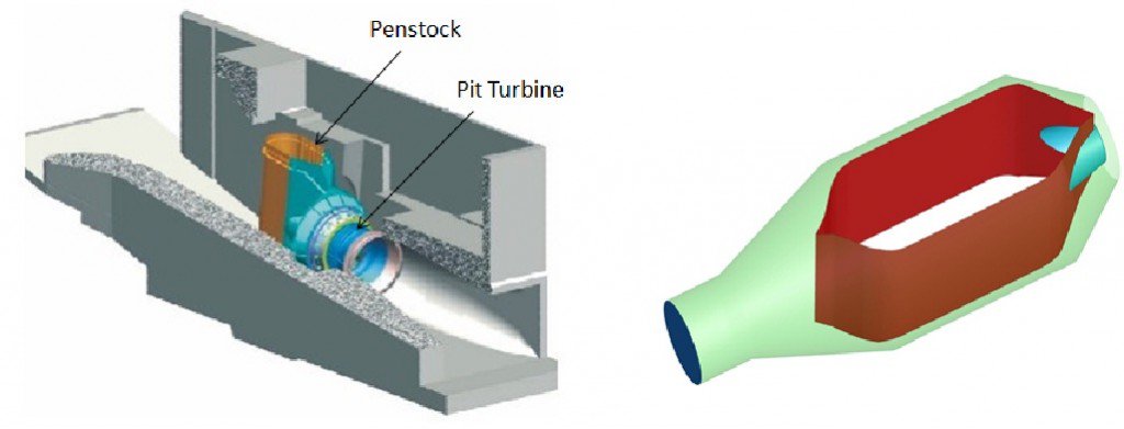
Power generated by the hydro turbine depends upon the available head and the discharge at the inlet of the stator. The head available at the inlet depends upon how best the water is brought from the source to the inlet of diffuser through penstock. Hence it becomes extremely important that water is brought with minimum head loss from the source to the inlet of the diffuser. This ensures higher hydraulic efficiency of the overall plant and structural safety. Water arriving from the source through penstock needs to be distributed to the hydro turbine for optimum usage, balancing and overall functioning plant. In this case, careful design of the distributor is of great important.
Key contribution of CFD in this study
In this current study, with the help of CFD we were able to determine the total energy losses across the penstock
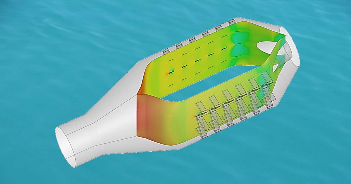
We were able to visualize the fluid flow inside the penstock with help of CFD simulation. The flow re-circulation zones were determined
The overall pressure distribution on the walls of the penstock was estimated
This has helped to figure out the high pressure zones and low pressure zones inside the penstock. Due to which, the areas prone to bulging were estimated. Based on this analysis some major geometry modifications were suggested
To avoid the bulging of the penstock some internal supports design was suggested
Simulation based optimization study of support design was carried out to reduce the total energy losses
The graph of the total energy losses for varying mass flow rates was plotted
CFD Methodology
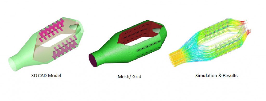
The fluid flowing through the penstock is water. To capture the water motion inside the flow path, conservation equations of mass and momentum are solved using finite volume method. The assumption of incompressible flow is made as water is mostly incompressible fluids at such operating conditions. Turbulent flow equations are solved using RANS based turbulence model. In all the calculations, isothermal flow equations are solved.
The typical workflow of CFD analysis is shown Figure
About author
Vijay Mali
Vijay is a technology explorer, a visionary and a product maker. As CBO of the company, he plays a critical role in defining the growh path of the company. He also leads the center of excellence (CoE) department at CCTech which is responsible for exploring new technologies & building a strategy to bring it to common designers. Vijay has over 15 years of experience in providing the CFD solutions for many complex problems. He has conceptualized many software solutions including the Pedestrian Comfort Analysis & Control Valve Performer app developed on simulationHub platform. Vijay is known for his transformative way of teaching and trained more than 500 candidates on complex topics like computational fluid dynamics and design optimization. He has delivered talks at various events and engineering colleges about CFD and its use in design optimization of a product. Vijay holds a master degree in aerospace engineering from Indian Institute of Technology (IIT Bombay).
Comments
Recent posts