
Thursday, October 04, 2012
Faceted Geometry Kernel – Mesh Boolean Technology
By
Sandip Jadhav
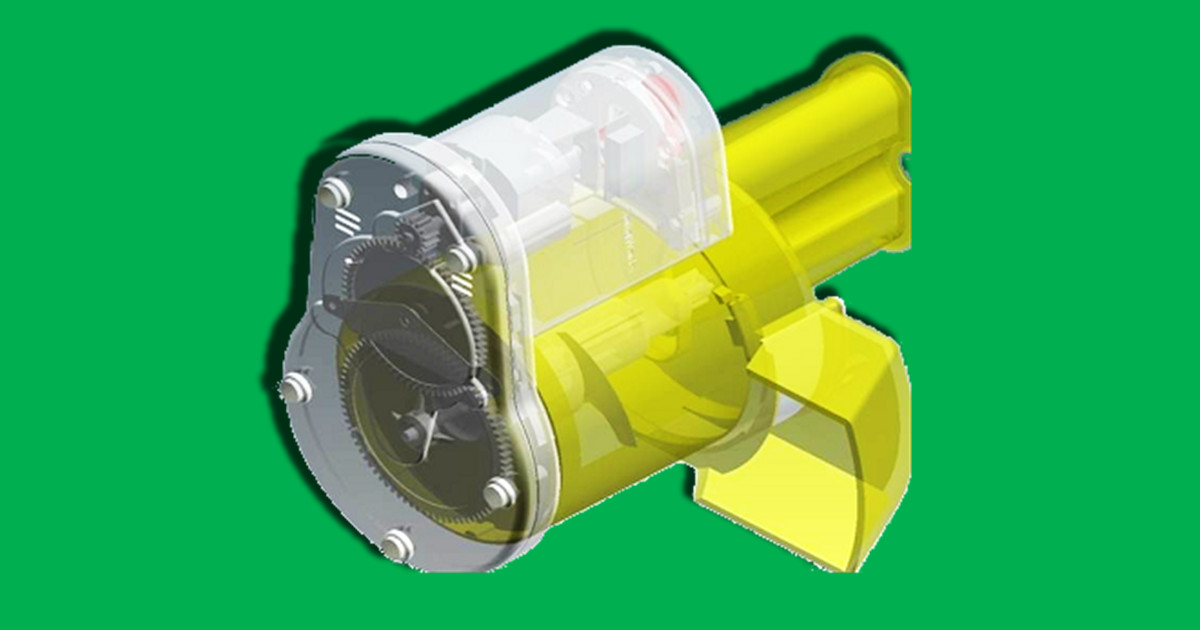
CCTech's research and development focused for past several year is in the area of mesh processing or discrete geometry processing. The key technological research outcomes are integrated into our mesh processing kernel named Faceted Geometry Kernel (FGK).
One of the core technology we developed in FGK is ability to perform Boolean operations on Faceted/Tessellated/Triangulated/Discrete/Mesh Geometries (all these words used interchangeable here).
Some of the salient feature of Mesh Boolean technologies are as follow :
Mesh objects can be multiple connected solids, multi-body solids, non-manifold solids, solid with internal void holes, solid X surface, surface x surface, non-manifold surfaces
Ability to handle point contacts, line contacts, plane contact
High floating point accuracy for intersections
Tolerant modeling to reduce the failure rate
Ability to retain original shape
Crisp intersection curves
Assembly models processing
If input is Faceted BREP Model ie Facet Information + BREP topology, the output solid after Boolean is Faceted BREP
Output Boolean Solid retains the Surface Parametrization
Surface - Solid combination can perform Punching, Slicing, Shelling operations
Boolean Operations on Triangulated Solids
Algorithm to perform 3D Boolean operations on CAD model are being developed from last 30 years. The successful implementation of Boolean operations on BREP made it one of the most popular underlying geometric modeling technology. However these Boolean operations are mainly used in NURBS base solid models.
Mesh objects as modeling representation is not very popular in Mechanical CAD (MCAD) industry. Industrial Design applications such as 3D Max, Maya used mesh object and they have various feature to process mesh objects.
CCTech is currently using mesh processing technology in various innovative applications in Mechanical CAD, Civil CAD, manufacturing simulation, CFD model preparation, oil and gas domain extraction, biomedical modeling and other. We believe mesh processing technology can be greatly leveraged on new Mobile, Cloud and internet applications for CAx vertical. Since it has very small memory and computation footprint as compared to NURBS base modeling.
Mesh Boolean Types
Boolean on mesh objects can be performed in two ways :
- Standard Boolean algorithm used in BREP
- Using Level Set Method to create approximate but quick Boolean
We have developed both these meshing Boolean technologies for different CAx applications. We found that in engineering application where the precise Boolean are essential one must use standard BREP based algorithm. However for various upfront simulations eg in manufacturing simulation for 3Axis or 5 Axis Milling simulation, going for exact Boolean would be a overkill. Here LSM based Boolean works wonderfully.
The rest of this article will elaborate first approach in detail.
Mesh Boolean Basics
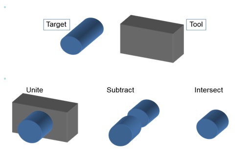
1. Target and tool
The operands of a Boolean are called the target and the tool. The target of a Boolean is the body you begin with, and the tool is the body you operate on it with. The target is modified by the tool, and the tool is deleted at the end of the operation. Following figure illustrate target, tool and possible Boolean output.
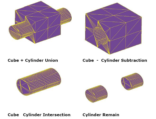
The following diagram shows the faceted Boolean perform on triangulated Cube and Cylinder.
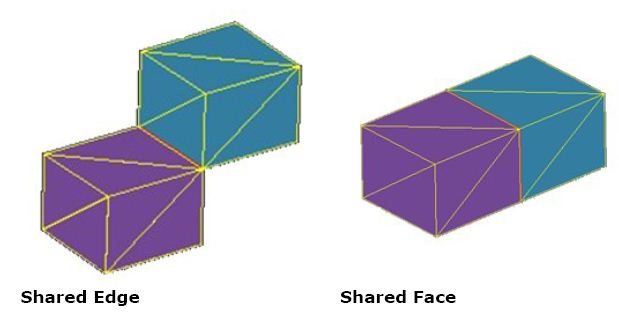
2. Non-Manifold or cellular Solids
In simple word, A manifold is a mathematical term for a object that locally resembles a line, a plane, or a space whereas Non-manifold Object is with point or line or plane contact between the solids. Single Solid body with multiple zone separated by face is called as cellular solid. Mesh Boolean can perform general body Boolean i.e. non-manifold boolean as shown in below figures.
3. Type of Boolean
Global Booleans : Global Boolean perform Boolean operations on whole bodies, taking a single target body, and multiple tool bodies, and applying the specified Boolean operation to the target. Because the operation is performed at the body level (by comparing all pairs of faces in the target and tool), the resulting body is guaranteed to be topologically consistent. Global Boolean, because of the nature of the face pair comparison, can be computationally expensive.
Local Booleans : Local Boolean (sometimes known as partial Boolean), tend to be very quick to perform compared to global Boolean. Rather than working at the body level, local Boolean use a set of faces from a target body, and a set of faces from a single tool body. User specifies these faces himself, and only the faces user specify are used in the Boolean operation. Restricting the scope of the Boolean operation in this way can drastically improve performance.
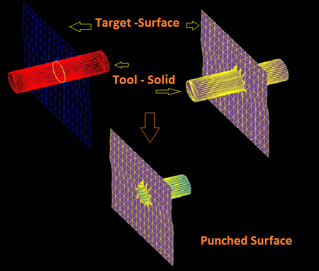
Sheet Booleans : When we use target or tool as surface and solid combination, the boolean are called as Sheet Boolean. If booleans in subtract operation target is solid and tool is sheet then one can perform trimming operation whereas target is sheet and tool is solid produces punching operation. Sheet Boolean can be subdivided in following types.
4. Trimming
When target body is solid body and tool is surface body and boolean option is subtraction, the output solid bodies can be trim solids as shown below figure. Trimming in particular is highly useful in trimming unwanted features or removing components during CAD Repair operations in downward applications such as CFD and CAE analysis geometry preparation.
Mesh Boolean Algorithm
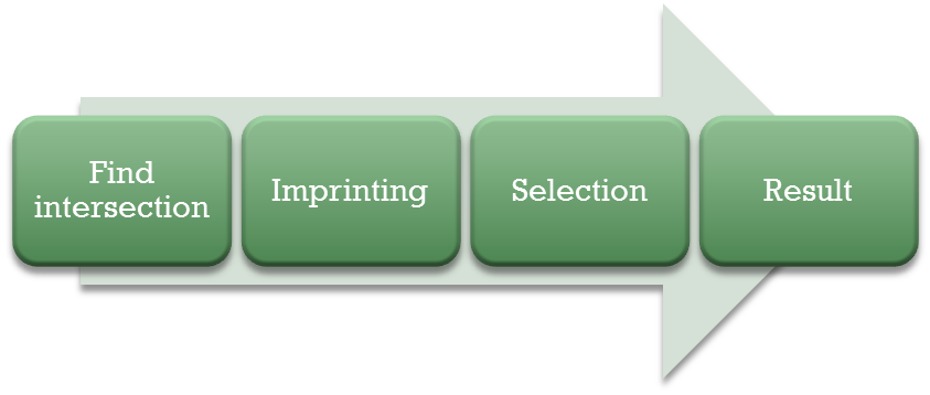
A Boolean operation may be a union, subtraction or intersection. Generally the input parameters are passed through option structure to create appropriate Boolean is created. By default union operation is performed. Faceted Boolean has four main important steps, those are intersection, imprinting, gluing, and selection:
1. Intersection
First step of a Boolean operation is to find the intersection between the target and tool entities. Since our underlying geometric entities are triangulated solids and surfaces, you have to perform polygon X polygon intersection over large set of entities in short time. The high level floating point accurate algorithms are used to make the intersections robust. The expected output at the end of Intersection is set points, set of curves. In geometries with curved overlapping surfaces one can get infinite number of intersections. Therefore obtaining correct intersection curved in this case is tricky task.
2. Imprinting
New geometric entities created in intersection operations need to be embedded in topological structure of target and tool bodies. This processing of topological embedding is called Imprinting. Once can expect new imprint edges and vertices at location of intersection. These imprinted edges and vertices form the boundaries of intersection between target and tool entities. These edges divide the faces of each body into face sets which are either inside, outside, or on the boundary of, the other bodies.
3. Gluing and Selection
The output of Imprinting process is new topological entities such as Faces, Edge and vertex. One need to stitch or glue these topological entities to create new shells. Such gluing of resulting sets of Faces can create multiple shells. Topological Shells gives new bounded regions.
4. Result
Newly form regions in above steps compartmentalize the physical space. The parts of physical space of the model which are to be kept or rejected are selected, according to the type of Boolean being performed. For example in case of Boolean addition operations one keep all the regions. If there is duplication region then those are deleted. Depending on expected result type such as manifold or Non-manifold, these regions are also required to be merged to form a cohesive physical space. In case of Boolean subtract operation, target-tool common regions are not added in final body. It is also possible that new target bodies might have lot more new faces due to imprinting operation. In this step those new faces are also merged whenever possible.
Mesh Boolean Implementation
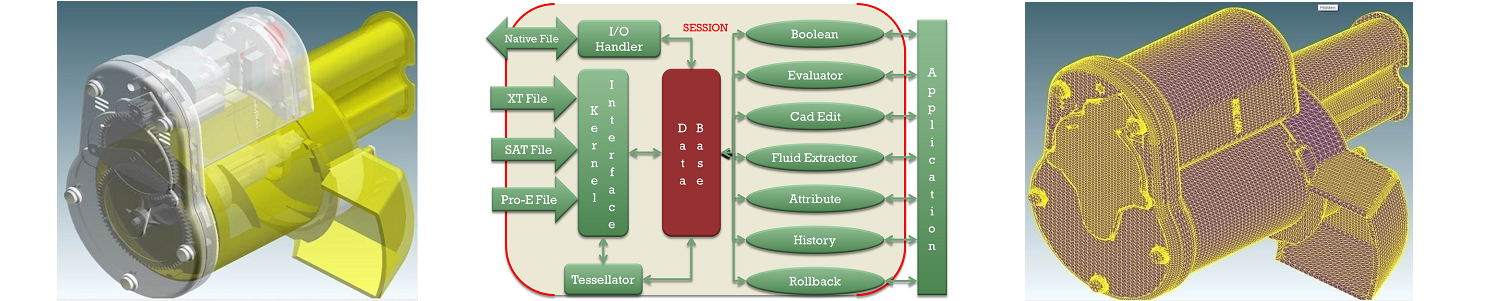
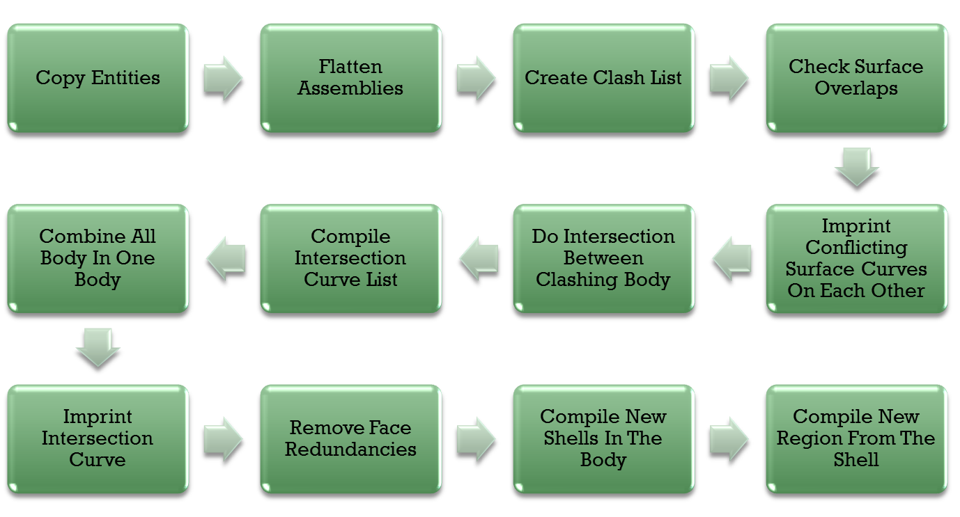
Implementation of Mesh Boolean algorithms expands above four steps into many micro algorithms. To handle the Boolean on assembly models, Non-manifold model further steps are added in main Boolean algorithm. Following flow chart shows important steps of mesh Boolean implementation. In next blog article we would discuss them in details. Do leave your valuable comment and feedback in comment section.
About author
Sandip Jadhav
Sandip is a successful serial entrepreneur in CAx space. He co-founded CCTech, LearnCAx, Zeus Numerix, and Adaptive 3D Technologies in the span of last twelve years. Sandip has more than 15 years of product development experience, in the field of CAD, CAM and CFD. He has done major contribution in conceptualizing, designing, and developing 3D CAD application, faceted geometry kernel, faceted Boolean, mesh generation software with automatic fluid volume extraction for dirty CAD assemblies.
Comments
Recent posts